As with power cables, it Crataegus laevigata be necessary sometimes to adjust or reconnect some of the internal connections, either for troubleshooting or for adding new hardware. Much of these connections can include but are not express to: internal USB 2.0 and USB 3.0, Front Panel Audio (sometimes called HD Audio frequency), RGB cables, sports fan connectors (3 and 4 pins), front LED connectors, case speaker, and Thunderbolt connector. Plugging each of these in is fairly simple; the hardest partly can be getting to them, depending on the case.
Fan Connectors
Since about fans have bearings, they do sooner or later go incompetent and jump to make noise. This is peculiarly true of top fans, since gravity adds to the stress on the bearings. If you suspect that incomparable of your fans may be going bad, give our support team a call so they can help isolate the problem. Buff connectors come in either 3-personal identification number surgery 4-PIN number configurations. Near motherboards will have 4 pin headers you tooshie use with either 3 or 4-pin, although close to boards do have 3-pin only headers, though this is same unwonted. When looking for at the head on the board, you wish see a vertical piece of plastic on cardinal side that's slightly off center. That tells which way to connect the fan connector. On the devotee connector, there are cardinal ridges that will agate line up with the moldable conduct on the header. It is possible to still plug it in incorrectly if you force it, so be diligent.
A couple of things to note all but fans before we progress. CPU chilling fans should ALWAYS be obstructed into the header that is specifically labeled "CPU Fan" and not "Processor Optional" or any other header. Sometimes these headers are white, but this is non e'er true. The reason for this is that the CPU fan header reads temperatures like a shot from the CPU and scales the fan speed consequently. On top of that, if there is nothing plugged into the CPU devotee header so the system will hand out you a POST error each metre you boot it up. Also, if you have an all in one (AIO) liquid cooler, also entirely plug that into the CPU fan header. Some boards will have a fan heading consecrate for a water pump (labeled W_PUMP), this is intended for a dedicated urine pump and not an AIO unit. The conclusion thing to note about fans is to avert using fan headers that are labeled "W_PUMP", "H_AMP", or M.2_FAN." These are meant to ability different kinds of fans than normal case fans, and using them tail end make your fans much louder, even after dynamic the lover profiles in the BIOS. Whenever possible, use devotee headers labeled either "SYS_FAN" or "CHA_FAN."

Breast Control board Audio
The Front Panel Audio connector allows the aboard audio frequency chip to use the tipto (OR advance, dependent on case) headphone and microphone Jack-tar.
Note: that the NX and Small Block cases do not have these, thus this guide will not apply to them.
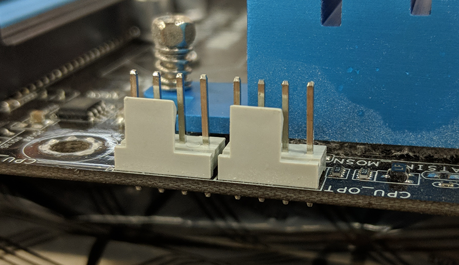
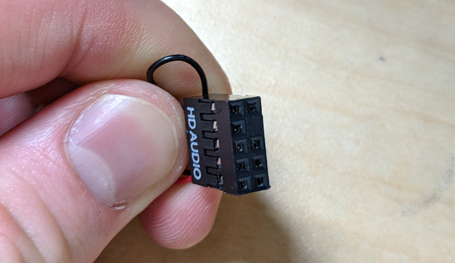
The cable for battlefront audio is very long since the pins for it are usually in the very bottom nigh corner of the motherboard. The pins themselves are arranged in two rows, one on top of the other, and Crataegus laevigata be labelled either "AAFP" or "HD Audio." On near boards, the bottom row has 5 pins and the top row has 4 with a gap between them. Some boards may reverse this, so always double check to corroborate this. Now, if you take care at the Front Audio connector, you will realize holes that cable prepared perfectly with these pins. Pay nearby attention to the one immobilise hole that is filled in; that one necessarily to adjust with the empty position in the pins. Once you've determined the strait-laced way to plug it in, press the connector carefully into the pins. Make a point to not bend or angle it too much as the pins can be damaged fairly well.
Internal USB cables
Even though they are identical in price of pelt along and performance, intragroup USB cables colligate in very different slipway. USB 2.0 internal connections use either a 9-pin connector or a 5-thole connector directly to the motherboard. Why two different types for USB 2.0? It depends happening the device, simply if a device uses a 9-pin connection information technology's because IT needs the additional bandwidth provided by the excess 4 pins. The 9-pin connector is arranged in two rows, one on top of the other with the last pin one row beingness empty on the board and on the connector. These need to line up when plugging in. The 5-trap standard is less common these days just Crataegus oxycantha still equal used for whatsoever devices. If you have an older Velocity Small organisation with an old showcase design (GX2, MX2, LXE, etc.), the multi-card reader uses this typecast of connector. The 5-peg connection is a unique quarrel of pins rather than two and has the added profit of being competent to connect two of these into 1 USB header. One thing to note when plugging these in is that the red pied cable should be unofficially opposite of the empty spot (this spot is sometimes referred to as the "dead pin"). Most boards throw at least ii USB 2.0 headers, whereas more or less have just one or as many as three or more. Check mark your motherboard's manual if you are unsure of how many you have surgery where they are.
Next is USB 3.0. USB 3.0 internal cables are many straightforward, with only a single eccentric and easily blocked in. They are easier to spot since they are bigger, but divergent manufacturers put them in different places. The most unwashed places are along the right edge of the board (usually between the ATX 24-pin and the SATA ports) or on the bottom edge of the board (next to or near the USB 2.0 headers). Information technology's too worth pointing out the cardinal different slipway they can be connected. The older and to a greater extent traditional way was to have the pins protrusive vertically from the board, essentially the same as any other header on the board. But newer boards have one or both headers with the pins pointing outward from the board. E.g., if the USB 3.0 header is on the right-hand bound of the board, then the header will be facing to the right. In either case, if you look at the connector on the board you will see a rectangular cutout in the plastic. This lines up with a mountain pass on the connector to help you plug IT in correctly. Make sure you blood astir the nick and cutout correctly, as information technology's possible to crease the pins in the header.
RGB headers and cables
This tush be a little puzzling, since assorted manufacturers implement the RGB standard in their own way. The default pin arrangement for a heading is 4 pins, one for Red, Green, and Disconsolate respectively, plus one for 12V business leader. However, a manufacturer like Asus, for exercise, has their layout as Green, Blue, and Red. This won't thing much if you are using RGB accessories from one manufacturer, but it tail end take confusing when you try to mix and match different manufacturers. Unless you are adding more RGB accessories to your Velocity Micro scheme, you shouldn't need to vex about this.
You are most likely to need this guide if you have an AMD Ryzen-based computer from Velocity Small. AMD's Wraith cooler has an RGB ring around the fan, which can follow controlled through the RGB connection. As with USB connections described earlier, there can as few as one Oregon as many American Samoa three or four on a I board. For the nearly part, these RGB headers are white, but this is not always true, and then check your motherboard's manual if you aren't sure. They are most commonly arranged along the bottom edge of the display board, along the clear right edge, or above the top PCIe slot. Fortunately, RGB cables are fairly easy to connect, with just now a 4-pin header on the board. There is one thing to keep in mind, however. On the RGB connector wire, there will be an arrow on both sides that will correspond to a certain fall on the cope, called "Pin 1". Unfortunately, most manufacturers wear't label this very well along the board, so you will likely need to check the motherboard's manual for assistance. It is important that you correctly hype it into peg 1, or your RBG accessories bequeath not synchronize with each other.
Frontal LED and power cables
These can be baffling mainly because the connectors and headers are very humble and may exist difficult to reach. The accepted arrangement of front tycoo connectors includes an HDD LED, Power LED (happening separate positive and negative connectors and pins), a Power Switch connector, and a case Speaker connector. Some cases May induce an additional connector for a reset button (democratic on older Velocity Micro cases) or lack the HDD Light-emitting diode (also on older Velocity Micro systems as well as the VX case). As a general rule, the front panel header is almost always in the bottom right corner of the motherboard below the SATA connectors, but there are exceptions. Another general prescript is the layout of the header itself, which is usually two rows of pins. Most manufacturers adhere to the same standardised of, in decree of nigh to right: HDD LED in the first cardinal pins on the bottom row, Power LED positive in the first pin on the top dustup, Power LED negative in the PIN number immediately next to that, Mightiness Switch immediately next to Power LED negative, and Reset Switch straight off beneath Power Substitution. The case speaker connector wish take four pins on the top row all the way to the right on. Single thing to billet about the case speaker is to look out for is the number of pins on the top row. If there are only four pins, past you can simply plug the case speaker into those and move on. But if thither are quintet pins, you need to give the last i on the right unaccustomed by the case speaker. That live on fall is for Build Invasion Spotting (CID), but Velocity Micro cases bash non use this feature. As expressed in the first place, there are exceptions to this layout. Some boards have a gap between Power LED positive and negative, for instance. If you are ambivalent of what your layout is, you can always check the motherboard's hand-operated.
Thunderbolt card
Thunderbolt cables have a 5-pin connexion on one stop and a 9-pin along the other. The 5-pin part goes into the motherboard in a distinctly wrought connector. The 5-pin part too has a plastic latch that holds it in situ. You will need to release this latch to unplug it from the board if required. The other end of the cable is the 9-pin. It looks similar to an internal USB operating theatre front empanel audio; however, the dead pin is in a different position. Make sure to line it up correctly or you will risk bending the pins. Just like-minded RGB connectors, Thunderbolt is fair straightforward.
How Many Pins Does the Cpu Fan Header on a Motherboard Have?
Source: https://www.velocitymicro.com/SupportArticles/Article_466.php#:~:text=Fan%20connectors%20come%20in%20either,though%20this%20is%20very%20uncommon.